Draw the vectors starting at the black dots. I figured it is first necessary to draw a free body diagram of the entire wheel and then apply the method of sections in which I would make cuts along specific regions of the wheel and determine the forces acting on them.

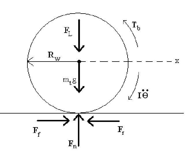
Free Body Diagram Of A Wheel Download Scientific Diagram
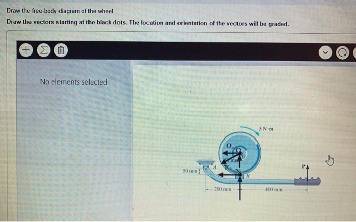
Note that the moment arms for the two spring forces are computed assuming a small angle θ.
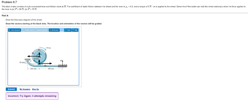
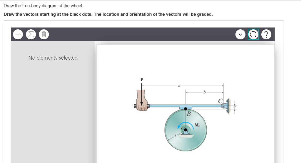
. Determine the moment required to initiate the rotation of the wheel and whether or not it is possible for the wheel to roll up the wall. Draw the vectors starting at the black dots. Draw the free body diagram of the wheel.
Eulers equation can then be applied about point O to minimize the number of equations needed. Be sure to consider Newtons third law at the interface where the two blocks touch. The sum of the forces acting on the 5 holes should equal 650 kgf.
The coefficient of friction between the. Draw the free-body diagram of the wheel and member ABC used as part of the landing gear on a jet plane. Problem 88 Thanks Question.
Identify the Contact Forces. Draw a free-body diagram for each block. To identify the forces acting on the body draw an outline of the object with dotted lines as shown in the figure.
Draw the vectors starting at the black dots. The distance between the two wheels is 8 feet and the center of mass is 3 feet behind and 25 feet above the point of contact between the front wheel and the ground. To draw a free-body diagram we draw the object of interest draw all forces acting on that object and resolve all force vectors into x and y-components.
Sketch what is happening. Free Body Diagrams on a LooptheLoop Roller Coaster Draw the free body diagrams for a coaster at the boom and top of a loop and write the equaons for the net force. The drawing shows a bicycle wheel resting against a small step whose height is h 0120 m.
In the section we will explain the step-by-step procedure of drawing a free body diagram. A Draw the free-body diagram showing the forces that act on the wheel. The block brake is used to stop the wheel from rotating when the wheel is subjected to a couple moment M_0.
Draw the free body diagram of the wheel. We must draw a separate free-body diagram for each object in the problem. The center of gravity is a distance c forward of the rear axle and a distance of h above the ground.
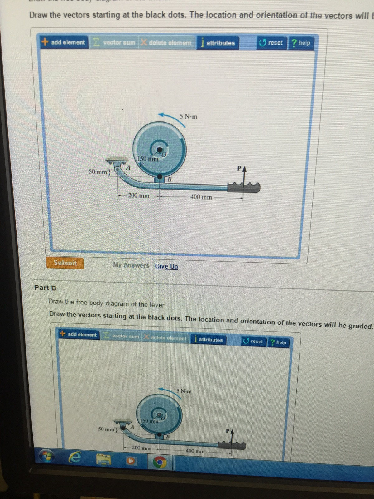
Draw the free-body diagram of the wheel and memberABCused as part of the landing gear on a jet planeThe hydraulic cylinderADacts as a two-force member and there is a. Part B Draw the free body diagram of the lever. Draw the vectors starting at the black dots.
The weight and radius of the wheel are W 250 N and r 0340 m respectively. Draw the free-body diagram of the winch which B 3 in. Consists of of aadrum drumofofradius radius 4 mm.
Draw the complete free-body diagram FBD of each of the bodies designated in the statements. Part B Draw the free body diagram of the lever. Determine the forces that act on the object.
Draw the vectors starting at the black dots. How to draw a free-body diagram. A 12 A 12 is the reaction force of block 1 on block 2.
The next step is to draw the free body diagram of the wheel as shown below. You can draw a free-body diagram of an object following these 3 steps. Draw a free body diagram of the car as it comes to a stop.
Draw a free-body diagram of an automobile of weight W that has a wheel base of length L during four-wheel braking. Radius ofof 6150 in. Free-body diagrams are important because they allow us to analyze an object in isolation without distractions.
Wheel is supported by a freely-rotating roller and the wall. Public Domain image no author listed. Free-Body Diagram Example 4.
A horizontal force F is applied to the axle of the wheel. Draw a free body diagram showing all forces and their directions Write equation of motion and derive transfer function of response x to input u chp3 15. Below Ive drawn a free body diagram of the wheel.
Write all the modeling. Significance A 21 A 21 is the action force of block 2 on block 1. The hydraulic cylinder AD acts as a two-force member and there is a pin connection at B.
HttpwwwphysicshelpcaGO AHEAD and click on this siteit wont hurtFree simple easy to follow videos all organized on our website. Draw the free body diagram of the wheel. A B P51 B C A P52 A B P53 C D A B P54.
The hydraulic cylinder AD acts as a two-force member and there is a pin connection at B. Problem 88 Thanks Posted one year ago. Connected to wheel using a flexible cable without skip on wheel.
Mg F net F N F net ma ma c The net force in the loop must be centripetal force F net F N. Draw the object in isolation with the forces that act on it. All Forcesr known and unknown should be labeled.
Draw the free-body diagram of the wheel and member ABC used as part of the landing gear on a jet plane. The weights of the bodies are significant only if the mass is stated. ItItisispin-connected pin-connectedatat its center C and at its outer rim is a ratchet gear having a mean A 502mm in.
The car shown below is moving and then slams on the brakes locking up all four wheels.
Solved Draw The Free Body Diagram Of The Wheel Draw The Chegg Com
Free Body Diagram Of A Wheel Download Scientific Diagram
Solved Draw The Free Body Diagram Of The Wheel Draw The Chegg Com
Solved Part A Draw The Free Body Diagram Of The Wheel Draw Chegg Com
Solved Part A Draw The Free Body Diagram Of The Wheel Draw Chegg Com

Solved Draw The Free Body Diagram Of The Wheel Draw The Chegg Com
1 Free Body Diagram Of A Wheel Download Scientific Diagram

Free Body Diagram Of The Wheel Download Scientific Diagram
0 comments
Post a Comment